
Tutorial: Reading and reconfiguring the XADC
Overview of the XADC
Xilinx 7 series XADC
The Artix 7 FPGA chip used on the Mercury 2 board is designed with the user in mind to provide high volume processing power for a relatively low cost. It has many powerful features including an on-board Analog-to-Digital converter (ADC) called the “XADC” available on 7 series FPGA devices provided by Xilinx. It is a dual 12-bit, 1 Mega sample per second (MSPS) ADC used to accommodate sampling for up to 17 auxiliary signals as well as including on-chip sensors for temperature and power monitoring.
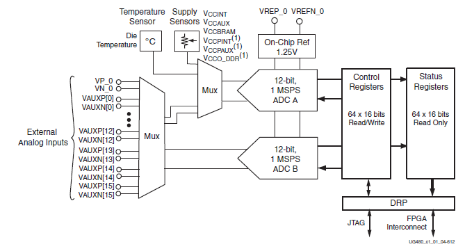
The XADC supports a wide range of operating modes such as single channel, sequenced channel, duel ADC simultaneous sequence, or one-pass sequence channel sampling; event driven or continuous sampling operation; unipolar, differential, or bipolar signal sampling; etc… The XADC can also be configured to power down its individual ADCs, rearrange the order of sampling when running in a sequenced channel operation, enable averaging of samples to reduce noise, set alarms for user defined voltage and temperature tolerance violations for on-chip sensors, etc… The image below shows the block diagram of the XADC as found in the datasheet for the device as provided by Xilinx. You can download the datasheets for the XADC by clinking on the button below.
Applying the functionality of the XADC to your project
With so much functionality available on the device, it’s easy to get lost in how to use it to do anything practical. Thankfully, Xilinx has included a wizard for Vivado to instantiate the XADC and create an IP block to initially configure all the control registers included in the XADC for your own ease of use.
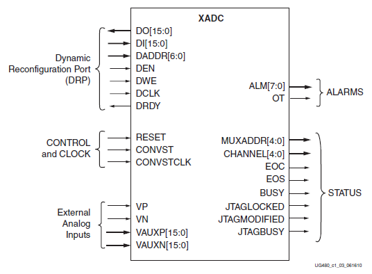
However, even with this initial configuration, converted signals cannot simply be read from the XADC. Instead, the digital values of the converted signals are stored in addressable status registers found in the memory of the XADC that will need to be retrieved. All operations communicating with the XADC to retrieve a converted signal or to reconfigure a control register for the XADC will have to be done through a synchronous read/write 16-bit interface called the Dynamic Reconfiguration Port (DRP). An illustration of the status signals and control signals available from the XADC including the DRP interface is shown below.
The Dynamic Reconfiguration Port of the XADC
The Dynamic Reconfiguration Port (DRP) is the interface used to access the control and status registers used in the configuration and operation of the XADC. Values of converted signals are written to the status registers when the end of conversion (EOC) or end of sequence (EOS) signal is raised high depending on the type of operating mode of the XADC.
In order to read any value to or from the XADC, the DRP’s enable (DEN) must be pulsed along with the desired address to be read to available at the DRP’s address input (DADDR[6:0]). If a read is desired, no other signal is necessary to retrieve the information that will be present at the DRP’s output (DO[15:0]).
If you wish to reconfigure one of the control registers, a write signal (DWE) must also be pulsed along with the enable signal, the desired address to be written to (ADDR[6:0]), and the value to be written to that specific control register by using the DRP’s input (DI[15:0]). These DRP control signals will only be effective for use when the DRP is ready (DRDY).
XADC Reading and Reconfiguration Tutorial
The purpose of this tutorial is to demonstrate how to:
Instantiate the XADC to use in your project
Initially configure the XADC for operation
Read the value of the converted digital signal using the Dynamic Reconfiguration Port (DRP)
Reconfigure the XADC using the DRP
In order to use the XADC, it must first be instantiated for use in your project. If this is not done, the status and control registers can be accessed, but only through the JTAG interface. To fully incorporate the functionality of the XADC and to access it with your own code, it must fist be instantiated. During this instantiation, the XADC is configured for operation and the signals and nets are given names for use in the top-level module that will be used to read the values of the converted signals via the DRP and also to re-configure the XADC. This top-level module is included in the .zip file that you can download by clicking the button below.
Get started!
Let’s get started by clicking the button to download the .zip file and extracting it in the file location of your desired Vivado 2018.2 project. We will be using this as a source file for our project.
For more information on how to get started with Vivado, please refer to the Getting Started with Mercury 2 tutorial. Once you are familiar with how to create a new project from scratch, we can adapt this knowledge to create a project from the existing VHDL file found above to create a practical interface that will read from the status registers and write to the control registers from the XADC.
Creating a new project with source files
We will deviate from the tutorial first by ensuring that the “Do not specify sources at this time” box is left unchecked. This will allow us to specify the VHDL files to be added to the project before it is created. After unchecking the box, click next to add the source files.

Source files are added by clicking the “Add Files” button navigating the explorer to where you unzipped the files for the Sine Wave Generator and selecting all the VHDL files. Then click “Ok” to complete the addition of the source files into your project.


Once you click “Next”, follow the rest of the instructions for creating the project as found in the Getting Started with Mercury 2 tutorial including selecting the device and adding the Xilinx Design Constraints (XDC file) to your project.
Instantiate the XADC
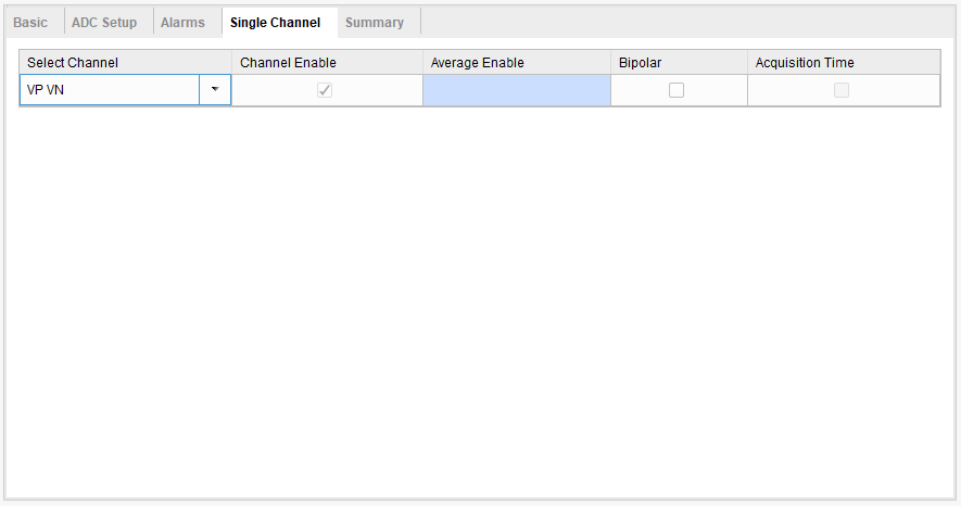
Next we will instantiate the XADC with a configuration of reading a single channel, unipolar analog wave with continuous sampling. The channel we will be obtaining samples from will be the Vp/Vn differential input that is included on the Mercury 2 board. The configuration of the XADC is not quite so important in this tutorial as we will be demonstrating how to reconfigure the XADC to sample the channels you wish and read the digital values from the XADC via the Dynamic Reconfiguration Port (DRP).
While the initial configuration may not be as important, it is important to instantiate the XADC in your program in order to access the signals and nets associated with the XADC in order to establish an interface with the XADC. We will instantiate the XADC by utilizing the XADC IP Wizard included with Vivado 2018.2. For more information on instantiating the XADC, refer to the XADC datasheets.
Instantiate the XADC using the IP Wizard
Once you have finished all the steps in creating a new project outlined in the Getting Started with Mercury 2 guide, left-click on the IP catalog and search for the XADC wizard by using the search bar that will show up in the IP Catalog window. Double click the XADC Wizard to start the Custom IP process.


Once you open the Custom IP window for the XADC, you will be greeted with many options for the initial configuration of the XADC. While some of the pre-configurations will not be necessary, it is important that the nets that will be used for reading the values and the reconfiguration of the XADC are obtained. As such, a few selections will be important to be made i.e. making sure the DRP is selected as an interface option.
In our source file, the module ports from another module called “XADC_IP”. It is important that this matches the name for the Component Name of the IP that will be created. The first thing we do, then, is change the Component Name so that it matches the entity found in our source file..
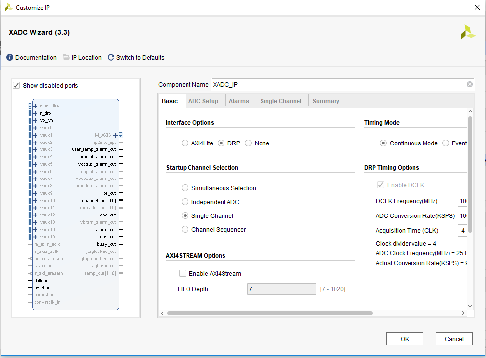
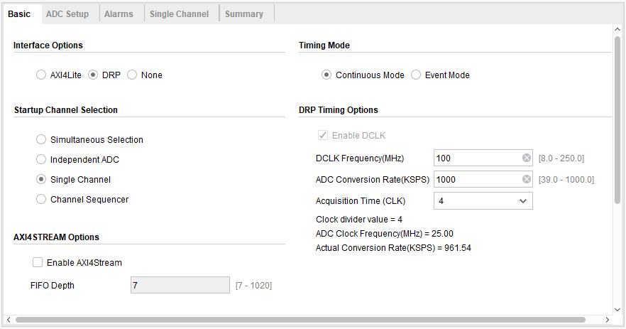
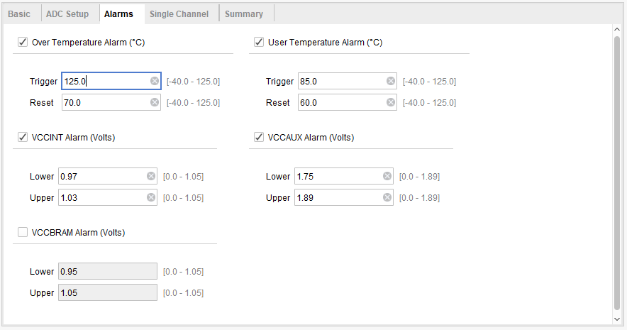
For our pre-configuration, make sure the following selections are made for each of the tabs available in the Custom IP window for the instantiation of the XADC:
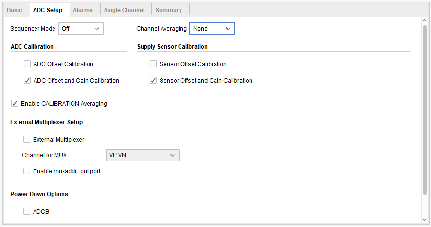
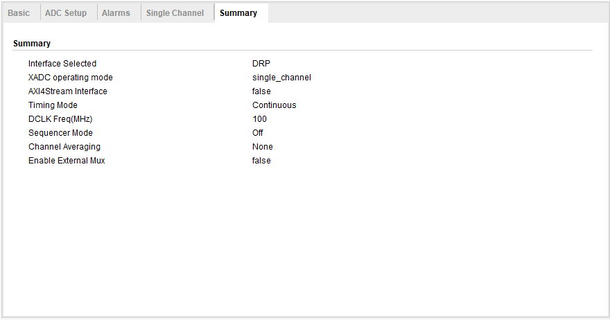
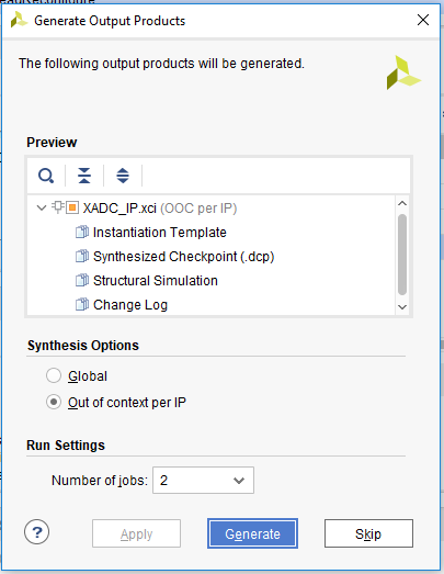
After all appropriate selections are made, finalize the instantiation of the XADC IP block by clicking “OK” and generating the output products as “Out of context per IP” in the Synthesis Options. Next, verify the addition of the XADC instantiation and the entity to your project by checking the Sources window for the appropriate hierarchy of source files.

The entity is the part of the module that is used to communicate with other modules through their entities or to the FPGA by mapping to a pin that is specified in the Xilinx Design Constraint (XDC). The architecture of the module is what designates how the module will work given the parameters passed through its entity.
You will note that all the modules are required to create the sine wave generator. The structuring of the project is done automatically in Vivado when the project is created. You can verify the hierarchy of the structure by expanding the “Design Sources” folder in the “Sources” window. Each level is illustrated by indenting sub-modules to the right.
Using the Mercury2_XADC Module
We are now ready to use the Mercury2_XADC module to obtain the converted digital signal from memory via the Dynamic Reconfiguration Port (DRP). This module automatically signals to the DRP a request to read the converted Vp/Vn value from memory that we pre-configured the XADC to read from. It also is used to reconfigure the XADC and automatically read the converted, desired channels. It can sample from 4 different channels, establish input signal type, and reconfigure the XADC for single channel and sequence channel sampling. The block diagram for the module is shown below.

Description of Mercury2_XADC Module Port Signals
ch_slct[3:0] is used in the reconfiguration of the XADC. Each active high index of the array corresponds to a channel from which the XADC will sample:
ch_slct[0] = 1 designates the XADC to sample the on-board temperature sensor
ch_slct[1] = 1 designates the XADC to sample the Vcc power supply voltage level
ch_slct[2] = 1 designates the XADC to sample the auxiliary power supply voltage level
ch_slct[3] = 1 designates the XADC to sample the Vp/Vn differential input
sig_type is used in the reconfiguration of the XADC. Setting it high at reconfiguration sets the XADC to sample the channel in bipolar mode while setting it low sets the XADC to sample the channel in unipolar mode.
smpl_mode is used in the reconfiguration of the XADC. Setting it high at reconfiguration sets the XADC to sample the channels in sequence while setting it low sets the XADC to sample a single channel.
reset is an active high signal that is used to reset the operation of the XADC and the state machine of the Mercury2_XADC module.
reconfig is an active high signal that is used when you wish to reconfigure the XADC. It places the Mercury2_XADC state machine in reconfigure mode where the configuration registers of the XADC are manipulated according to the state of the XADC Configuration Signals.
The External Analog Input is a differential input that corresponds to channel 3 in the XADC. The XADC is pre-configured to read from this input when the instantiation of the XADC is done according to this tutorial.
ch_stat[3:0] is an array of flags that indicate to the user that the converted 16-bit digital signal is available. Each index of the array corresponds to a channel whose converted digital signal is made available at the module’s output:
ch_stat[0] = 1 indicates that the converted 16-bit digital signal for the on-board temperature sensor is available
ch_stat[1] = 1 indicates that the converted 16-bit digital voltage level for the Vcc power supply is available
ch_stat[2] = 1 indicates that the converted 16-bit digital voltage level for the auxiliary power supply is available
ch_stat[3] = 1 indicates that the converted 16-bit digital signal for the External Analog Input is available
dgtl_val is the 16-bit output of the module that is read from to get each of the designated channel’s digitally converted signals.
alarm is an accumulation of the XADC’s alarms OR’d together.
Obtaining the Converted Digital Value from the DRP
Using the Mercury2_XADC module, obtaining the converted digital value of the channels you are monitoring is automatic. It includes a state machine that monitors the XADC’s and DRP’s status signals to appropriately send a read request and produce the converted digital signal to the 16-bit output of the module.
In the case of this tutorial where our XADC is pre-configured to sample the external analog input, the module automatically produces the 16-bit value at the end of each conversion. All you need to do is read from the module’s dgtl_val output.
Reconfigure the XADC at Runtime
Using the Mercury2_XADC module, we can also reconfigure the XADC at runtime. We can do that by supplying the XADC Configuration Signals available from the module as desired and pulsing the reconfig input high for at least one clock cycle. This places the module’s state machine into reconfiguration mode, monitors the XADC’s and DRP’s status signals to appropriately send read and write requests along with the addresses and values that are to be entered into the XADC’s configuration registers.
After reconfiguration is complete, the module automatically obtains the digital values of the desired channel(s) and produce(s) them at the output of the module, dgtl_val. The appearance of each channel’s digital signal is made known with a status signal from ch_stat[3:0]. A description of this is made in the section “Description of Mercury2_XADC Module Port Signals”.