
Getting Started with Mercury
Let's get started with Mercury! This simple tutorial will demonstrate how to take your design written in VHDL, compile and synthesize it using Xilinx ISE, then program the bitstream via USB.
Step 1: Download and install the design tools
Xilinx offers a free FPGA design suite called ISE WebPACK. For the Spartan-3A you must use ISE 14.7:
https://www.xilinx.com/support/download/index.html/content/xilinx/en/downloadNav/design-tools/v2012_4---14_7.html
NOTE: You must install Xilinx ISE 14.7 (October 2013) to support the Spartan-3A.
If you are using Windows 10, please see these instructions.
The Mercury Programmer burns a bitstream to the flash chip on the Mercury board.
It is available for download here:
http://www.micro-nova.com/mercury/programmer
Step 2: Create a Xilinx ISE project
After installing ISE, launch the Project Navigator. This is found in:
Start > Xilinx Design Suite 14.x > ISE Design Tools > 32-bit Project Navigator
From the "File" menu, select "New Project..."

After pressing "Next", we are presented with a variety of project settings.
Select the specific device (XC3S200A for the ME1B-200M & ME1B-200, XC3S50A for the ME1B-50), package (VQ100) and speed grade (-4). Select the hardware description language to be VHDL.

After clicking "Next", we are asked to confirm our project settings.

After clicking "Finish", we are greeted with a fresh, new project window!
Step 3: Add the Mercury user constraints file
Next, we must add a user constraints file (UCF). This is very important; it is here that we specify:
- Pin name and corresponding location
- Pin voltage standard (LVTTL, LVCMOS, etc)
- Timing constraints (clock period and duty cycle)
Below is an excerpt from the Mercury UCF file, dealing with the clock and four LEDs. The physical pin location for each of these signals is specified. (For example, check the schematic, and one would see that pin 43 on the FPGA is connected to the 50MHz oscillator.) The 3.3V LVTTL voltage standard has also been specified; this is discussed further in the Spartan-3A datasheet. For the clock signal, we have specified a period of 20 nanoseconds and duty cycle of 50% for the 50MHz oscillator. (Later, any part of our design using the clock will be analyzed to see if it is capable of running at the clock period specified here.)
   NET "CLK"       LOC = "P43" | IOSTANDARD = LVTTL ;
   NET "CLK"  TNM_NET = "CLK";
   TIMESPEC "TS_CLK" = PERIOD "CLK" 20 ns HIGH 50 %;

   NET "LED<0>"    LOC = "P13" | IOSTANDARD = LVTTL ;
   NET "LED<1>"    LOC = "P15" | IOSTANDARD = LVTTL ;
   NET "LED<2>"    LOC = "P16" | IOSTANDARD = LVTTL ;
   NET "LED<3>"    LOC = "P19" | IOSTANDARD = LVTTL ;
Download, unzip it, then add it to the project by right-clicking the FPGA "xc3s200a-4vq100" in the hierarchy and selecting "Add Copy of Source..."

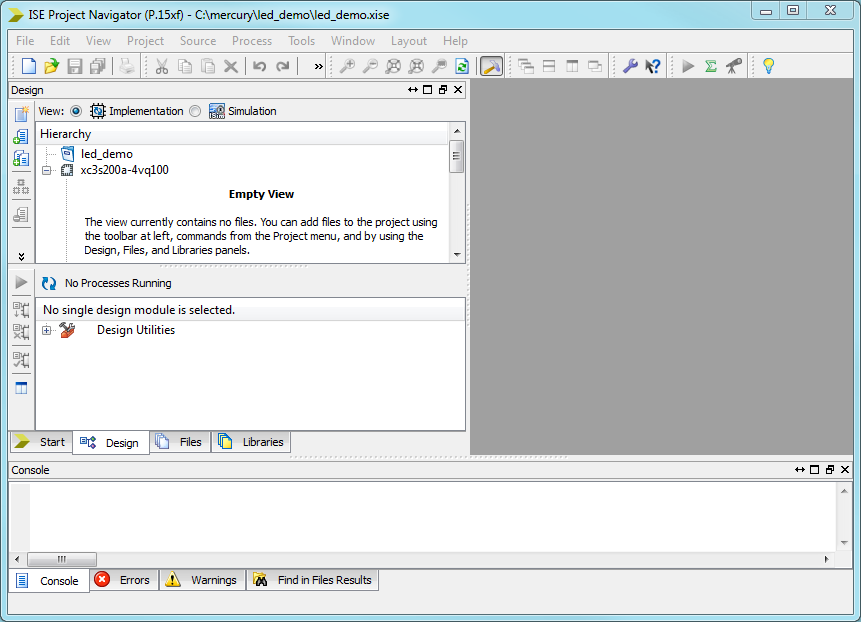
The UCF file has now been added to the project.

Step 4: Write some VHDL code!
Let's create a VHDL file and make a simple design. Right-click the FPGA "xc3s200a-4vq100" in the hierarchy list, and select "New Source..."

We want to create a "VHDL Module". Let's call it "led_demo".

Click through, and we now have a blank VHDL file in ISE.
Let's go ahead and code a simple example that flashes the LEDs on and off, with a period of one second.
library IEEE;
use IEEE.STD_LOGIC_1164.ALL;

entity led_demo is
    port(
        CLK : in std_logic;
        LED : out std_logic_vector(0 to 3)
    );
end led_demo;

architecture rtl of led_demo is

  signal count : integer range 0 to 49999999 := 0;
  signal pulse : std_logic := '0';

begin

  counter : process(CLK)
  begin
    if clk'event and clk = '1' then
      if count = 49999999 then
        count <= 0;
        pulse <= not pulse;
      else
        count <= count + 1;
      end if;
    end if;
  end process;

  LED(0 to 3) <= (others => pulse);

end rtl;
We want to flash an LED: on for 1 second, then off for 1 second.
To achieve this, we have written a "counter" process (that runs on the 50MHz clock) and counts from 0 to 49,999,999. After reaching the maximum value, it resets "count" register to zero, and flips the state of "pulse" register. All four LEDs have been wired to "pulse".
Step 5: Compile our design!
Let's go ahead and compile our design.
First, we must right click "Implement Design" and select "Process Properties..."
Make sure the box "Allow Unmatched LOC Constraints" is checked. (Our project only uses the four LED ports and the CLK port. Our UCF file contains entries for these ports, and a lot more! Without checking this box, the compiler will throw an error for each port entry in the UCF file that we do NOT use in our design.)

Next, right click the "Generate Programming File" button.

Xilinx ISE will now synthesize, implement and generate a bitstream for the design. This process takes about a minute for this simple design, but for bigger designs can take much longer. The "Synthesize" process takes the hardware described in VHDL, and infers the logical building blocks (registers, state machines, adders, etc.) that were described. The "Implement" process takes this design and tries to implement it using the resources available on the FPGA.
After running, there should be a green checkmark next to "Generate Programming File". Click "Design Summary/Reports" to view some helpful info.

Here we see that our design has consumed 1% of the slices available on the xc3s200a FPGA.
"All Constraints Met" means that the design has been analyzed for timing, and will operate properly with the 50MHz clock that we specified in the UCF file in step 3.
Step 6: Program the Mercury board
Now, let's program the Mercury board with the bitstream we just generated!
Connect the Mercury board to the PC via USB. Launch the Mercury Programmer app, and clock "Connect". The status bar in the lower left portion of the window should say "Connected". Select the "led_demo.bit" file that was created in the root of the project directory.

Then click "Burn" to write this file to the FPGA.

The progress bar will scroll by as the flash chip is being written to. This process should take about 10 seconds.

The flash chip on the board has been programmed, and the FPGA will immediately boot using the newly programmed bitstream. (Since this is stored on flash, the bitstream is non-volatile.)
The LEDs should be flashing: on for one second, off for one second!

We are now up and running with Mercury!